|
|
|
Solar Thermal Photovoltaics
|
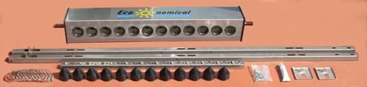
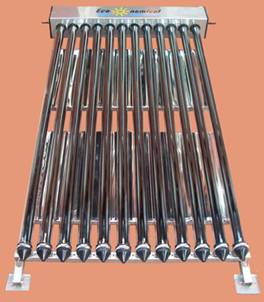
Assembling an Eco-nomical evacuated tube panel Check and identify the components of the panel. In this example an ECO-47-1500-12 panel is used, but the same procedure is used for all the panel types. Be careful not to knock the tubes. If the tubes are stood on the ground, leaning on a wall or similar, rest the end on a piece of cardboard or other soft material.
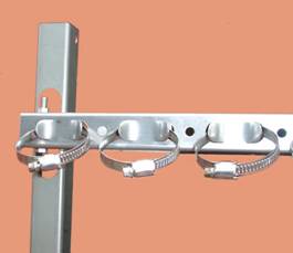
This picture shows the manifold, side bars, base bar, tube clips, end caps, bolt pack, thermal transfer paste, and feet. Not shown are the reflectors, and the tubes which are supplied preassembled with the heat pipes. It is possible for the inner, copper manifold to move slightly relative to the manifold case if the manifold has been dropped on its end while in its box. This manifests itself by the heat pipe pockets no longer being concentric with the tube holes in the manifold case, which makes it difficult to install the tubes. If this is the case, gently tap the 22mm copper pipe at the appropriate end with a piece of wood until the manifold is correctly aligned once more. Note that there are two types of tube fixing. If you have the screw cup type fixing, see the instructions further down this page. Open the tube clips by unscrewing the screw until the band separates from the screw block, and then, one by one push the loose end of each band through a housing on the base bar. For a neat appearance of the finished job, push them all through in the same direction. Push the end of the band into the screw block, and do up a couple of turns. If the band is hard to start, rotate the screw backwards a little and try again. Take the side bars and examine them. Near the bottom there are two upstanding lugs to which the base bar is bolted. Note that the side bars are handed because of the additional holes for mounting the reflectors. The sides with the extra holes go on the inside.
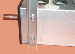
Fit the side bar to the base bar as shown, using one of the longer bolts to fix it. Do not over tighten. Repeat for the opposite side bar. Now the manifold can be fitted to the assembled frame. Lay the manifold on its side on the ground, and fit the side bars to the captive bolts. Note that the holes in the side bars are elongated to allow some adjustment to suit the tubes.
A good starting position is to let the end of the side bars rest on the ground when the manifold is also lying on the ground as shown above. Notice that the reflectors have a bolt hole at each corner. Locate the first reflector in the frame and insert and fasten a bolt. The other three bolts are fastened, and the procedure repeated for the other reflector.
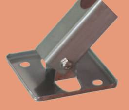
The feet are fitted to the base of the frame, although they may be omitted if unnecessary.
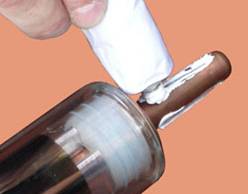
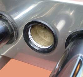
At this stage the assembly would normally be fastened to a roof. Now the tubes can be inserted into the manifold. With the assembly lying flat on the ground, thermal transfer paste is applied to the heat pipe bulb to ensure a good thermal contact between the heat pipe and the manifold.
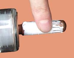
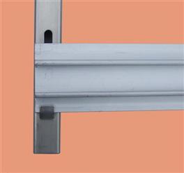
Spread the paste over the bulb to create an even film. Smearing the residue on the manifold seal will make inserting the tube easier. Have a cloth handy to wipe your fingers! With the top end of the tube above the manifold, the bottom end of the tube is fed carefully through the first clip on the base bar. The clip should be a very loose fit at this stage. Then the top of the tube is inserted into the manifold. Take care to locate the heat pipe bulb in the receptacle in the manifold. Twisting the tube helps to start the tube in the seal. Push the tube home. Slide the end cap over the tube and under the tube clip. Ensure that the tube is positioned such that the clip lies on the parallel part of the tube. Tighten the clip just sufficiently to prevent the tube from moving. Do not over tighten, as this may cause the tube to fail. Repeat for all tubes. For a neat appearance, ensure that all caps are level and all clips face in the same direction. Following these instructions correctly should result in a panel which looks similar to this one, although yours may have more tubes. Note that there is an alternative design of tube clamp which uses plastic screw cups. If you have one of this type, please note the following additional instructions. The screw type cups use a different, extruded aluminium bottom rail which sits in a clip on the side rails.
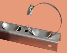
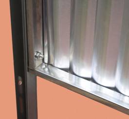
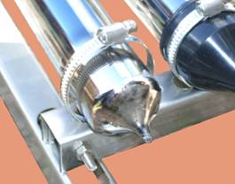
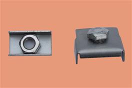
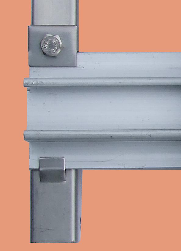
Fasten the rail with one bolt through the top hole. A rectangular profiled washer holds the nut captive under the frame, and a metal clip clamps the rail in place.
The rail is clamped as in the picture below.
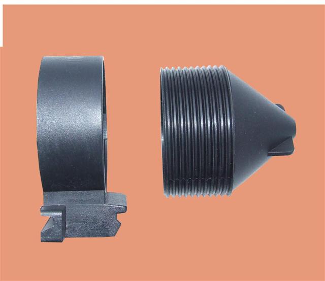
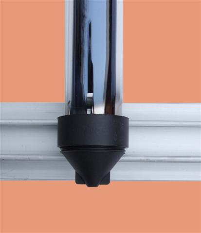
The tube supporting cup is in two pieces which screw together.
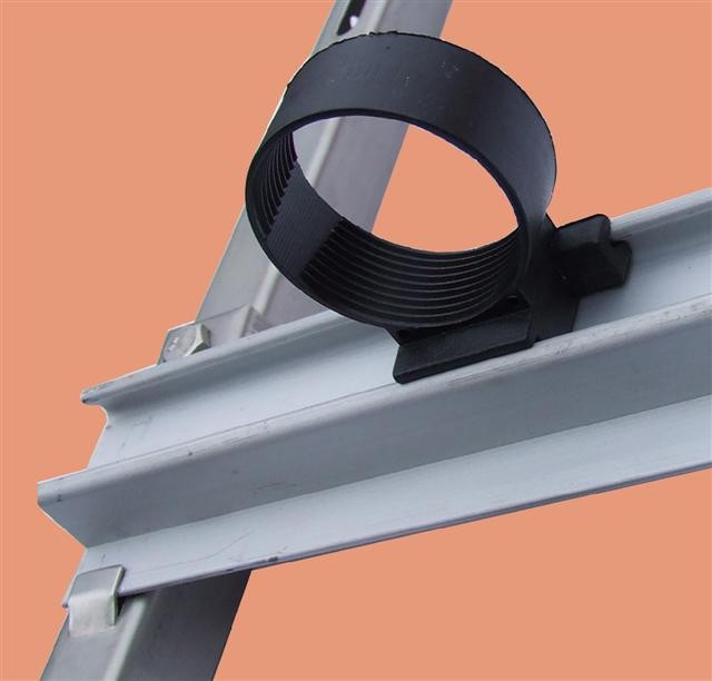
The ring snaps in to the mounting rail, or alternatively can be slid in from the end.
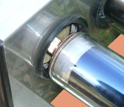
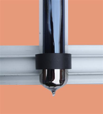
The bung in the top of the tube is different with this type of fixing, as shown below. Note that this type has no copper collar above the bung.
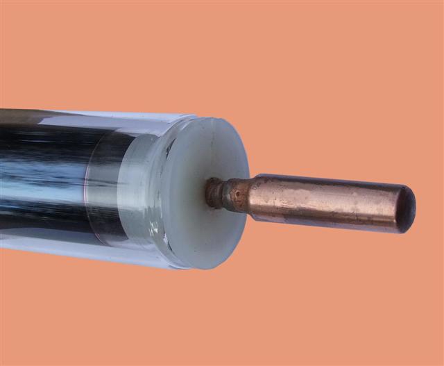
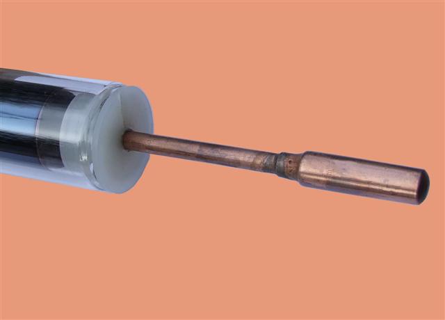
Insertion procedure into the manifold for this type of tube is slightly different. Pull the heat pipe out from the tube about 150mm as shown below.
After the rest of the frame and manifold has been assembled, and all of the tube rings are in place, slide a tube in from the top, angling it to avoid the manifold. Push it through until the top clears the manifold. After applying heat transfer paste as shown previously in these instructions, hold the heat pipe tube below the bulb and push into the manifold pocket. Once the heat pipe is fully inserted, slide the glass tube into the manifold until the base of the tube protrudes about 15mm below the retaining ring, such that when the screw part of the ring is installed most of its thread is engaged. Note that the glass tube should not be pushed up as far as it will go.
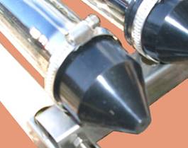
Now screw the bottom of the cup into place to retain the tube. Do not overtighten, gentle hand tightening is sufficient.
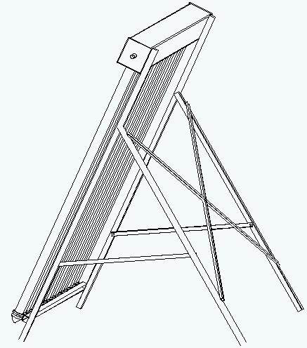
The flat roof stand (purchased separately if required) fits together as shown in the following picture.
The "vertical" legs are similar to the side rails of the collector, the side braces and cross brace are of lighter construction. Feet, not shown on this drawing, are attached to the bottoms of the side rails and frame legs. Thirty tube collectors have a centre leg and a corresponding leg on the stand with an additional cross brace.
|
Send mail to
SW@eco-nomical.co.uk with questions or
comments about this web site.
|