|
|
|
Solar Thermal Photovoltaics
|
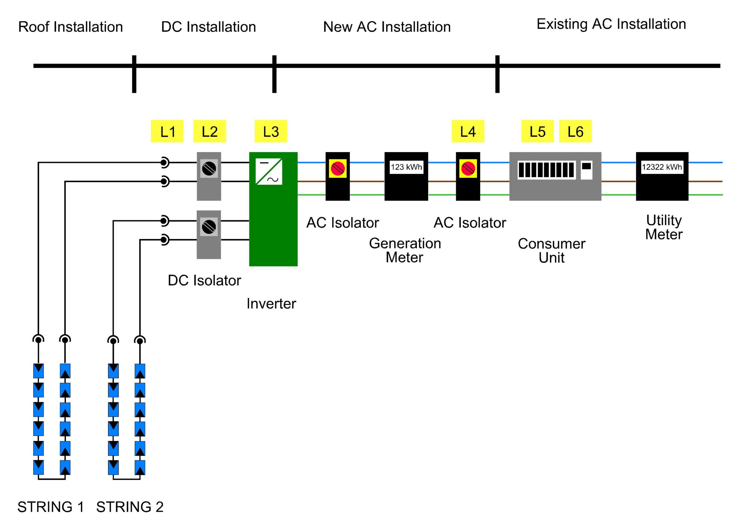
Photovoltaic Installation Notes Note: Since this page was written, new rules have been introduced which effectively require you to have your pv system installed by an MCS registered company. Please see here for more details. The following information is intended to give a competent person an overview of the installation of a domestic grid tied pv system under the G83 procedure. Such an operation requires alteration of and addition to the electrical system of a house. The work is controlled by part P of the building regulations, and a mass of other statutory and non statutory regulation. Contrary to popular belief, this does not mean that it cannot be carried out by the householder. However, the work must be carried out correctly (and understanding and following the multitude of minor wiring regulations is no trivial task), and then certified by a competent organisation, either a suitably qualified electrical contractor, or an inspector appointed by your local building control people. Note that while the above is true as far as complying broadly with legal obligations is concerned, dealing with power companies own regulations, obtaining grants and preferential feed in tariffs (getting paid for your electricity) all have there own procedures. Go through your plans with your chosen power company and your local building control thoroughly, and don't just assume it will turn out alright! Remember also that pv modules are unusual in that they cannot be switched off. If there is light falling on the panel it will produce power. Even a small array of only a few panels can easily provide a lethal shock, and even a non lethal shock is highly dangerous when received on a roof, where it may cause a fall due to loss of balance. To minimise the hazard, complete the DC wiring before connecting the panels, avoid working with both positive and negative cables simultaneously (eg use separate junction boxes, if required, for each side), cover the modules, install at night under artificial light, and/or use suitable insulating tool, gloves etc. If you are unclear about any of the terms used, please see our glossary here. Installation Overview PV modules are mounted on a roof or other suitable structure and connected together in series to form strings. Series connection increases the output voltage, typically to a few hundred volts. If voltage would get too high, then additional strings are created and connected in parallel, which increases current. The maximum voltage and current figures depend primarily on the inverter selected, although all connected equipment must obviously be suitable. An inverter converts a DC supply of varying voltage to AC of a fixed voltage and frequency. The amount of power produced by the array needs to be recorded, using a gross generation meter. This item is not supplied by the DNO or power company. The pv supply is then connected to a standard way in a consumer unit. The utility meter must be suitable for import/export use, some are and some may need replacing. If necessary this will be done by the power company, but they may make a charge. Generally the size of the array is limited by financial considerations. Decide how many modules are affordable, then consider which inverter to use, if necessary with two or more strings. The system is governed by engineering regulation G83/1, which is used by the power companies to regulate Small Scale Embedded Generation (SSEG) installations. Schematic layout of grid tie pv installation Roof mounting PV panels must be securely mounted on the roof, with the same requirements for orientation as solar thermal collectors (see here). A sufficient space must be left between the panels and the roof, generally 100-150mm to allow good ventilation. Higher temperatures result in loss of performance. Many proprietary systems are available for this, with a bewildering array of rails, clips, connectors and brackets. Eco-nomical has such a system, see our pv products page. However, these are fairly expensive, typically £50-£80 per panel. It is possible to do much the same thing with standard aluminium extrusions and roof bolts. This idea is also covered on our pv product page. Note that if a string is in partial shade, the reduction in output is significantly greater than a pro rata reduction would suggest. Try to position the modules such that the whole string remains unshaded. Even something as small as a TV aerial can cause significant loss of performance. The schematic above shows two strings connected to the inverter, mainly to illustrate the need for a DC isolator for each string. Often a single string is used in domestic pv installations. DC equipment selection For the modules supplied by Eco-nomical, all DC equipment including cabling must have a minimum rating of: Voltage: Voc x 1.15 Voc and Isc are provided by module manufacturers, see here for Sharp NU180 figures. Obviously they must be summed appropriately for strings (connections in series add voltage only, connections in parallel add current only). These safety factors must be applied because under certain conditions differing from standard test conditions the values can exceed those stated. Any DC installations exceeding 120Voc require double insulation for all their components including cabling. Note that ordinary household twin and earth cable is not considered to be double insulated, despite having two layers of insulation material. Isolation Isolators (switches) are required by regulations
in several locations in the pv installation. The main reason for these is
to allow work to be safely carried out on the various components without risk of
shock. Pv installations are unusual in that they can be live from both
sides, so a single isolator has little effect. Note that the DC side
requires special DC isolators (and indeed other items, such as connectors, must
also be DC rated), AC switches will quickly degrade due to arcing caused by DC.
The switches must be double pole, mounted near the inverter. If a long
cable run is present in the building, an additional isolator should be used near
the cable point of entry to the building. Cabling Cable runs should be kept as short as possible, and (obviously) selected so as to meet voltage and current carrying requirements. It is advisable to use special pv cable, with special pv plug connectors, as this ensures compliance. Any connector plug used must be DC rated. PV plug connectors are proprietary, commonly used MC3 and MC4 connectors are actually trade names of the Multi Contact company, although other companies manufacture compatible plugs. DC Fuses Generally, for systems with 3 or fewer strings,
DC string fuses are not required, provided the following rule is obeyed. The rule is that the minimum current
rating for the cabling must be: Inverter Inverter selection is an important part of the pv system design, made easier by configuration software supplied by the manufacturer. The software will suggest array size, inverter capacity (maximum power), no of strings, cabling requirements and maximum DC voltage and currents. The software provided by Fronius is available here. Inverters utilise a clever technology called maximum power point tracking (MPPT) which adjusts the voltage and current from the array to maximise power output. Inverter efficiency generally declines at low power levels, so it is common practice to slightly undersize the inverter, as can be seen from the sizing software. Note that the inverter must be earthed like any other electrical equipment. The inverter must be certificated to meet the requirements of G83. One of the more important requirements is to ensure that the inverter shuts down the pv system in the event of a power cut, in order that the supply network does not carry unexpected voltages during such an event. The inverter monitors the power supply and ensures that it is within expected limits. This can lead to unwanted shutdowns, for instance in the case of overvoltage on the grid. The system should be monitored carefully, particularly during its early operation, to ensure that this does not occur. Generation Meter This is used to record the number of units generated by the pv array. It is a requirement of most power companies for their SSEG schemes. It must be approved by OFGEM, who publish a list of suitable meters. They are required by the DNO even if the inverter records energy production. Connection to Consumer Unit The system is usually connected to the household supply using a spare way in the consumer unit. Despite the obvious contradiction, the pv side is still considered the load and the household side the supply for connection purposes (although if an RCD is fitted as a protective measure, the pv side is considered to be the supply side (see BS7671 regs 712.411.3.2..1.1 712.537.2.2.1)). The AC line from the inverter to the consumer unit should be a dedicated circuit, and may not have socket outlets, or current using equipment connected to it. Short circuit protection, typically an MCB in the consumer unit, must be provided for the AC cable. Warning Labels A number of different warning labels are required to be displayed at the locations shown on the schematic as follows. L1 Do
not disconnect DC plugs under load - turn off AC supply first Approvals Notification of grid connection must be must be
made to the Distribution Network Operator (DNO), either before or on the day of
connection. G83 paperwork must then be submitted within 30 days.
|
Send mail to
SW@eco-nomical.co.uk with questions or
comments about this web site.
|